Forum Replies Created
-
AuthorPosts
-
Zootalaws
MemberPPS – you don’t need to clone the git.
You do need the TinyG updater app installed, as it uses ‘bossac’ to program the Due.
My copy is in ~/Downloads so the path is: /~Downloads/TinyG-Updater.app/Contents/Resources
Edit the .sh file:
sudo nano DueFromOSX.shIn the line: FLASH_TOOLS= replace the path with the path above (assuming you downloaded the TinyG updater app to Downloads.
The first 3 lines of the script should read:
#!/bin/bash FLASH_TOOLS="~/Downloads/TinyG-Updater.app/Contents/Resources" BOSSAC=$FLASH_TOOLS"/tools_darwin/bossac/bin/bossac"-
This reply was modified 8 years, 6 months ago by
Zootalaws.
MemberI omitted: unplug the Due after programming and connect the native USB port, then connect using a terminal program using 115200,8,N,1. I use CoolTerm.
tinyg [mm] ok>
[fb]  firmware build             78.02
[fv]  firmware version            0.97
[cv]  configuration version       5.00
[hp]  hardware platform           3.00
[hv]  hardware version            0.00
[id]  TinyG ID                   02130215d40
[ja]  junction acceleration  100000 mm
[ct]  chordal tolerance           0.0100 mm
[sl]  soft limit enable           0
[mt]  motor idle timeout          2.00 Sec
[pdt] pause dwell time            0 uSec
[ej]  enable json mode            0 [0=text,1=JSON]
[jv]  json verbosity              2 [0=silent,1=footer,2=messages,3=configs,4=linenum,5=verbose]
[js]  json serialize style        1 [0=relaxed,1=strict]
[tv]  text verbosity              1 [0=silent,1=verbose]
[qv]  queue report verbosity      0 [0=off,1=single,2=triple]
[sv]  status report verbosity     1 [0=off,1=filtered,2=verbose]
[si]  status interval           250 ms
[gpl] default gcode plane         0 [0=G17,1=G18,2=G19]
[gun] default gcode units mode    1 [0=G20,1=G21]
[gco] default gcode coord system  1 [1-6 (G54-G59)]
[gpa] default gcode path control  2 [0=G61,1=G61.1,2=G64]
[gdi] default gcode distance mode 0 [0=G90,1=G91]
tinyg [mm] ok>
It literally took me as long to do as it took to write those two posts – I had a Due on my desk and had never done this before, so it’s not rocket science.
MemberOn a Mac mini:
Downloaded the compiled bin file from: http://synthetos.github.io/g2/binaries/TinyG2_Due-edge-078.03-default.bin
In terminal (I already have git loaded)
git install https://github.com/synthetos/g2.gitmove the downloaded bin from downloads to ~/g2:
mv ~/Downloads/TinyG2_Due-edge-078.03-default.bin ~/g2/Resources/TinyG2-OSX-Programmer/TinyG2.binPlug a USB cable from the computer to the Programming port of the Due (the one closest to the power jack).
cd ~/g2/Resources/TinyG2-OSX-Programmer/

./DueFromOSX.sh -f TinyG2.bin -p /dev/cu.usbmodem*
Forcing reset using 1200bps open/close on port /dev/cu.usbmodem241311 wait... Starting programming of file TinyG2.elf -> TinyG2.bin on port cu.usbmodem241311 Erase flash Write 119380 bytes to flash [==============================] 100% (467/467 pages) Verify 119380 bytes of flash [==============================] 100% (467/467 pages) Verify successful Set boot flash true CPU reset.Done. You now have a G2 core Due.
Peasy…
If you don’t have git installed, download the zip file from https://github.com/synthetos/g2 (clone or download – choose ZIP) and unzip it to a folder – you could leave it in Downloads and change the paths above to reflect that – ~/g2 becomes ~/Downloads/g2, etc.
-
This reply was modified 8 years, 6 months ago by
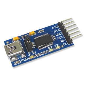
MemberOr just buy a ready-made FTDI to USB device and connect it via the serial pins
~$3
 Member
another solution to a failed USB interface is to use an ‘external’ USB to serial device, as used to program devices like ESP1s
Connect it to the serial pins on the TinyG and you have the same result, without the need to do smd soldering.
MemberFurther, I have connected via Bluetooth and the serial I/f, esp8266 and both serial and USB, and (slowly) through a LoRa connection and the serial I/f.
USB is perfectly feasible, isn’t a protocol, and is supported for bidirectional traffic, natively. When you tell your arduino to report back a condition using Serial.println() you are doing exactly that, using the USB port for Comms. The FTDI chip or whatever brand is implemented as a seria-to-USB controller is there for a reason, is controllable and is capable of megabit speeds (I regularly talk to my WeMos devices at ~1Mbit over USB).
You may find locating a cable with compatible connectors on both ends difficult, but that’s what solder’s for.
MemberWhats your use case?
In essence, the TinG is an arduino, so you want to control one micro controller with another? Where does a human get a look in?
You can control using the serial lines or SPI or ICSP, just like a uno or nano.
You can iterate the TinyG code on an arduino, so it stands to reason that all the interfaces on an arduino are supported.
But I can’t see what you are trying to achieve.
MemberSSRs don’t work well with digital signals unless they are tiny.Any relay that can handle ~100V DC in NO mode will work.
The advantage of the WeMos relay is that it already has all the circuitry needed to work with 3.3V signals.
There are a bunch for Arduino as well – I have an 8-way relay board I’m using for hydroponics switching.
Like these: 1Ch with optocoupler for 99c. From China, so shipping will be weeks, though.
Or these at ~4x the price for identical unit from the US
MemberHere is my relay to run my spindle. The 3.3V provided by the TinyG is fine for the job and M03/M05 works perfectly:
https://www.dropbox.com/s/rh7dr2xnpo6ebis/relay-tinyg.jpg
Another thing I thought of, Thomas: as you are using a Raspberry Pi already, rather than using the TinyG js page, you might want to have a look at Chilipeppr: http://chilipeppr.com/tinyg
Nothing wrong with the JavaScript page, but chilipeppr is a few technology leaps up the chain.
-
This reply was modified 8 years, 6 months ago by
MemberJust as an FYI:
I have installed my TinyG onto the back of my gantry and fitted my limit switches to the gantry and the X-axis itself, triggered by screws protruding into the path of the gantry on X and Y axes, rather than running them all the way around the machine. Initially I used a long USB cable, but now have a wireless solution using John Lauer’s fine Serial Port JSON Server a spare Raspberry PI 2 and Chilipeppr:
http://chilipeppr.com/tinyg#com-chilipeppr-widget-serialport-download
This cuts down on the length of wire needed to half the width of your gantry – 750mm/2 in my case.
I didn’t bother with shielded cable, I just braided AWG18 hookup wire to reduce the chance of EMF interference. Ask your daughters how to braid 🙂
John’s Chilipeppr solution isn’t perfect for third-world internet connections, but you don’t have to use it – just the SPJS component.
You can use the Universal GCODE Sender, for example:
-
This reply was modified 8 years, 6 months ago by
MemberThe fact that it’s exactly 8x the distance may point to a ‘stuck’ bit. Maybe it could be resurrected using some of the AVR tools that check and diagnose every location in the chip and memory? Atmel Studio is the main tool for AVR-based systems.
The chip used in my V8 board is the ATxmega 192A3-AU
https://www.microchip.com/avr-support/atmel-studio-7
Setting up Atmel Studio for the TinyG: https://github.com/synthetos/TinyG/wiki/Project-Setup-For-Atmel-Studio6.2
This is the full test program for the V8 boards – you can run through it yourself at home – it is very detailed: https://github.com/synthetos/TinyG/wiki/TinyGv8-Production-Test-Instructions-for-Revision-2-Tester
Without knowing how the speed controller/PSU is constructed, it’s hard to know how it works – a momentary switch triggering another switch circuit within the controller, a power junction that feeds all of the power between the poles…that you have to keep the link connected shows it’s not a momentary switch (like in a PC PSU).
I’ve found the same unit on multiple sites in China, but there’s little information on the spec of switch needed. If you have anything with a switch rating, that will help. If it’s rated at amps, all the power goes through it, but you said there was zero volts between the poles, which lends itself to being a low-power link to indicate power should be allowed to flow inside the controller. The size of the cable they used as a shunt was what led me to believe it was just a link in the power path.
And lastly, it might be a problem with the TI DRV8818 on your X-Axis. Have you tried moving that motor to a different axis? You can buy a cheap polulu-type driver for a 3D printer (or pinch one off a GRBL board for testing) and wire it as an external driver before going down the route of testing every memory location and processor function. That would be my second step, after using a different axis for testing (use Z axis and leave your Z disconnected during the test).
Good luck.
MemberThomas/Carl,
Oops. Yeah. Wiring cock-up, by the looks.
You’ve got a 110VDC power on/off switch running through a 3.3V Tiny – might be toast. Might be lucky and it’s only that pin that’s toast, in which case you can play with the source and get another pin to do the same function, or use a different function that controls a logic pin – like the ‘cool’ pin.
The SPIN function is a logic switch, meant to be wired to a device that supports logic – 3.3, 5, 12v, it doesn’t matter as it’s the other end that has to see the rise in the level to determine the change of state. I often send a 3.3V logic to a 5V receiver – such as an Arduino. It’s input at the 5V end, so as long as the V rises enough from the Tiny to trigger the logic, all good. Doing it the other way round, not good.
That ‘controller’ is a transformer from 110vAC to 110VDC but they have built in a PWM speed controller. The ‘speed controller’ is a potentiometer, it can be wired to a Mach3 controller, and the TinyG!
You can achieve what you want.
Check the speed controller pins for voltage = it shouldn’t have any (you never know with these Chinese boards… I’ve seen all sorts). PWM needs to have a signal, ground and +xV. If the signal is happy with ~3V, you’re good to go. if not, you will need to shift it to use the PWM on the TinyG. You will also need to provide it with voltage and ground
However, the Tiny is a fragile little beast and I would use voltage and level shifters, as well as a diode to absorb any spikes. It’s a small amount of money compared to replacing the TinyG.
I use cheap adjustable voltage levellers. You can get them from Sparkfun or Ebay for cents. I also use signal level shifters, again from Sparkfun or EBay.
At the least to control the spindle power on/off you need a relay that can handle NO current of whatever amps that thing draws – and triggers with a small DC voltage (<5V) – you may get a car relay to trigger that low…
Personally, I would look at something like this rather than that ‘speed controller’ which you have no idea of the pedigree: https://www.inventables.com/technologies/spindle-speed-controller
And read this: http://blog.inventables.com/2014/06/shapeoko-upgrade-quite-cut-spindle-with.html
As to power relays, I’ve literally just set one up on the TinyG to control my AC Kress 1050. I used one from WeMos, designed for their 3.3V ESP8266. I use it in NO mode. It’s already set up to receive a 3.3V logic signal.
https://wiki.wemos.cc/products:d1_mini_shields:relay_shield
I’m on 220V, but it can handle NO (Normally Open – it’s powered-off state. In NO mode, when power to the relay goes off, the relayed power connection is broken. In NC – normally closed – mode, when the relay power goes away, the relayed power switches on – used in some situations, not in CNC.) current of 5A(250VAC/30VDC), 10A(125VAC), MAX:1250VA/150W – I guess it depends what side of the transformer the power switch is on. The spindle is rated to 500W at 110VDC. If that transformer is pulling more than 5A AC I’d be surprised, but I know nothing of your North American wiring standards. 10A is the max here in 220V land, but that gives you a heck of a powerful device on the end – like a 3500W heater or 2500W electric hammer 🙂
If you’re not sure, give me more info and I can work something up. It’s a bit like working in the dark here…
MemberAnother, illustrated method: https://matterhackers.dozuki.com/Guide/Tuning+Motor+Current/37
MemberYou can use your finger – if it’s too hot, it is too hot to hold your finger on for ~5 secs. As in ‘bloody hell!’, not ‘ouch’ 🙂
I tuned mine using the ‘Polulu v-ref’ method, just using a multimeter: http://reprap.org/wiki/Pololu_stepper_driver_board
Seems to be just dandy.
MemberYou haven’t given us any information regarding your X-axis – belt or screw, if belt, what pitch/gear, if screw, what pitch/travel (i.e. 2mm belt, 12mm screw, etc.). Without knowing your transport its hard to work out.
Movement is a function of step angles, pitch of transport and stepping.
So, the calculation is:
a step angle of .9 degrees – 400 steps/rotation
8 micro steps per step – 3200 micro steps/rotation
a full rotation travel of 2.0050 requiring 3200 micro steps to complete.For my Z-axis:
1 step at 1.8deg on an 8mm/rotation screw (2mm pitch) is going to travel 0.04mm
1 microstep is 1/8 of that or 0.005mm
1600 Microsteps per rotation to move 8mm.So my screw is, at best, accurate to .005mm
For my X-axis I have GT2-3 belt on a 20-tooth pulley
One rotation of the motor pulls 20 teeth through at a pitch of 3mm for a travel/rotation of 60mm or 2.36″
One step gaining .3mm (200step/rotation)
One microstep gains .0375mm (1600step/rotation).You have (pardon my reluctance to work in base 12) 50.9mm gain per revolution on a .9deg/step motor with 8 micro steps/step.
That works out to:
1 step gaining 50.9mm/400 or 0.1275mm/step
1 microstep gaining 0.016mmSo, your step moves 0.1275mm, my step moves 0.3mm, as you would expect with your double-resolution stepper.
I would set my TinyG to:
[1ma] m1 map to axis 0 [0=X,1=Y,2=Z…]
[1sa] m1 step angle 1.800 deg
[1tr] m1 travel per revolution 60.0000 mm
[1mi] m1 microsteps 8 [1,2,4,8]
[1po] m1 polarity 0 [0=normal,1=reverse]Yours is set to:
[1ma] m1 map to axis 0 [0=X,1=Y,2=Z…]
[1sa] m1 step angle 0.900 deg
[1tr] m1 travel per revolution 2.0050 in
[1mi] m1 microsteps 8 [1,2,4,8]
[1po] m1 polarity 0 [0=normal,1=reverse]Can’t see anything wrong with that.
I did notice your power is set to ‘always on’, where mine is set to ‘in cycle’.
You also didn’t say what happened when you didn’t use the ‘spin’ pin. Does it all work normally?
So – as you have reloaded the latest firmware, we can rule that out – the areas to look at are your basis for calculations: What drive system at what resolution are you using? What are your exact stepper motor models?
More info would help.
-
This reply was modified 8 years, 6 months ago by
-
AuthorPosts