Forum Replies Created
-
AuthorPosts
-
SecondSource
MemberGreat thanks for the information cmcgrath5035.
All the best.MemberOh the other thing was re. the TinyG2 pinout diagram at:
https://github.com/synthetos/g2/wiki/Arduino-DUE-Pinout-for-g2coreIs this pinout likely to be consistent with the latest build of g2core? Or have pins changed over time?
Thx
MemberExcellent thanks a lot for the speedy reply!
That clears it up. Much appreciated.Membercmcta82 your schematic looks fine in principle, but note that the capacitors are the wrong way around, you want the – side to GND and + side to the port pin.
You probably took your capacitor symbol from the tinyG schematics; I am guessing they are using 0.22uF ceramic non-polarized caps on the tinyG board, and sometimes non-polarized caps are shown with a straight line next to a curved line, despite that more commonly being used with polarized parts. On the tinyG schematic they seem to add a + symbol to indicate the part is polarized and omit it when NP.
In any case you have the right idea, let us know if that solves your problems.
MemberWhat kind of limit switch are you using? I am using an optical sensor, I found these on Ebay: http://www.ebay.com.au/itm/131135211065
The detector is a transistor junction that shorts when there is no obstruction in the gap, and when the light is blocked it turns off, and the pin’s internal pullup drags it HI. I had to remove a resistor on the sensor’s circuit board to isolate the output since I am driving it with 5V.
So basically the emitter is connected to arduino ground and the collector to the processor pin. I have mine set to Limit + homing.
Here are a few ideas, you might have already tried some of them:
1) Turn the motor supply off (arduino is still live), then put a multimeter or an oscilloscope on the pin and check that you are getting 3V3 when the switch is not activated, then trip your switch and check for 0V. Make sure it goes all the way to 0V if your switch type allows it. If you have a CRO, drive the motors and check that there are no spikes / dips / etc. you should have a steady 3V3
2) Try adding a stronger pullup to the 3v3 supply, say 1k or so? If you are using NO switches you will pull about 3mA only when the switch is closed. This might improve noise immunity.
3) Are the switch wires intertwined with the motor wires for neatness? Try running the wires away from the motors and their wires, or try using screened cable and grounding the screen. There might be crosstalk injecting noise into your limit switch line.
4) I forget what the default parameters are but try issuing $$ and make sure your switch_type set to NO. I have recompiled the code to hardcode the settings so it doesn’t revert after a reboot (no EEPROM on DUE)
Let us know.
MemberThanks a lot cmcgrath5035, actually the information you supplied initially helped me a great deal; it made a lot of sense in conjunction with the Due pinout diagram found here:
http://www.robgray.com/temp/Due-pinout-A4.pngI was able to confirm that these are the correct pins and they have pullups internal to the processor. I have been testing the homing cycle with optical limit switches with some success.
But I have noted a situation where if I execute a homing cycle on say x axis only, using the X axis pulldown menu in chillipeppr, or with GCode manually, it homes correctly. But if I then immediately issue another homing command, it will start from zero and start moving negative and crash the carriage. It’s almost like when you start a homing cycle there is a period where the homing sensor is not being checked.
Maybe this is something for another thread?
MemberApologies, now that I test pins 9-11 they read 0v, 3v3, 0v3 respectively, which is another indication that these may not be the right pins to use. Any thoughts would be much appreciated.
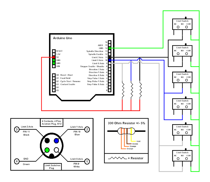
MemberSorry not sure what happened, the image URL is
https://lh4.googleusercontent.com/-FhXABwKcb-I/UvMhBLTESlI/AAAAAAAADCI/kfE-f7jkrwc/s800/cnc_limit_switch_c3.pngMemberLink deleted
-
This reply was modified 11 years, 5 months ago by
SecondSource.
MemberThanks for the information and followup cmcgrath5035, much appreciated!
-
This reply was modified 11 years, 5 months ago by
-
AuthorPosts