Forum Replies Created
-
AuthorPosts
-
InPhase
MemberMy point is, how is it a gcode issue if it will run everywhere but edge and master? But when all was done, the graphic on the tgFX screen proudly displayed a perfect picture but the wood under the spindle was like Congress.
Alas, it matters not because I’ll be out of the game for a bit.
-
This reply was modified 11 years, 8 months ago by
InPhase.
InPhase
Member
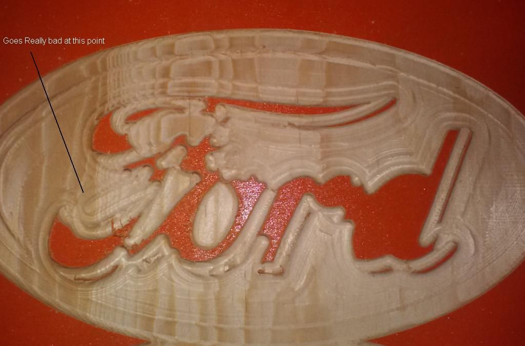
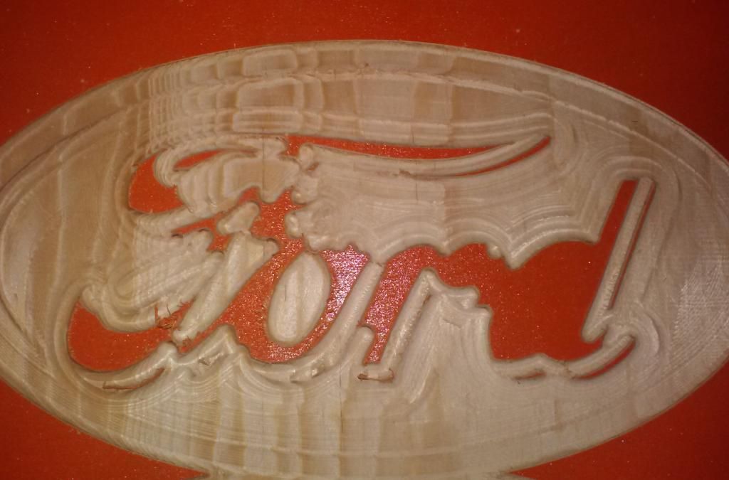
What I have labeled there is the tail I was referring to earlier. If I run this under Mach3 on my machine or someone else’s it is fine. If I run it under Coolterm using the dev branch with TinyG it is fine.If I run it under edge or master branch using Coolterm or tgFX, I get what you see in that picture. And I mean identically. At first I thought I had a mechanical issue. Then I checked for electrical problems with grounding and shielding. Then I changed the type of gcode the design software produced. Then I scanned the gcode line by line looking for a problem.
Other gcode files also run somewhat askew as well, but that Ford logo became my default test file. This is the result from dev branch:

-
This reply was modified 11 years, 8 months ago by
InPhase.
InPhase
MemberIf you want to donate one, I’d be happy to test it out for you LOL!!!
InPhase
MemberWell, I tell you, I have had the most amazing luck. Last night I heard one tiny rumble of thunder and woke this morning to find my blueray player and cable box dead as well as the surge protector they are plugged into. And out in the shop, the computer and TinyG are smoked too! LOL! But I’m an optimist.
To answer your questions, I first spot trouble around line 6800. There is a triangular island of material beneath the “r” and “d” that the machine rapids over to clear away. It doesn’t completely get it all and this is the first sign. Soon afterwards it moves over to begin finishing the letter outline and it just plows right into the tail coming off the left side of the letter “F” and it only gets worse from there. Coolterm does the same.
You won’t be able to see this with the motors inhibited because the screen simulation is fine. But the actual workpiece is pure carnage. As far as using dev, I understood the risk. I bought a $129 driver that wouldn’t run in any way but dev, so I took a chance. Now here I sit, with no driver and no computer to push it with LOL!
I have another computer I can set up, I just need to get another board now.
InPhase
MemberI did not build the adapter. I changed the code so that I could leave the outputs from the xmega to the drivers floating in case I did decide to make the adapter. What I found out was that stray capacitance would tend to cause the enable lead on motor 1 to fluctuate since it was floating. I was just too stupid to realize it when I made that post.
When I run that gcode, about 2/3 of the way through using any firmware but the dev branch, the little left hand tail of the “F” is the first sign of trouble. It cuts the outline of it at the very beginning, but towards the end, after it completes the ellipse, it will go back to “F” and plow through that tail and proceed to just eat away everything it has done. I posted picture of it in another thread.
It happens at the exact same spot using the edge and master branches, even 380.06. The dev works well, but it doesn’t work with tgFX, so it’s kind of a damned if you do, damned if you don’t scenario. That is, the master and edge work with tgFX, but don’t run the gcode well. And the dev runs the code ok, but doesn’t work with tgFX!
InPhase
MemberSo, I managed to slog my way through making the changes to system.h and making a new hex file. What an experience that was. Anyway, the motor outputs don’t seem to be floating. Motor 1 is still enabled all the time. And the rest of them seem to be pulled low.
Short of cutting the traces on the board or buying something else to drive my machine, what else can I do, why hasn’t the system.h change been effective?
InPhase
MemberOK. I tested 380.06 and it fails at exactly the same spot the master and previous edge build do. The only firmware that even comes close to working for me is the dev. And it works pretty good but just misses a couple of spots that leave extra hand work to do.
So, if you don’t mind, shoot me that hex file and I will build my adapter circuit and use mach3 until a firmware is released that works better. EMAIL: frontdesk@alabamainphase(dot)com
Thanks again.
InPhase
MemberYou guys are great. I don’t want to pursue this unless I absolutely have to. I drew a circuit diagram last night and gathered the parts I will need to put it together, but I want to give 380.06 a shot and see if it corrects the minor problems I’m having with the dev branch and the major problems I had with 380.05.
So, simply disabling the motors ($md) won’t be sufficient for backfeeding the drivers with an external signal? My adapter circuit design includes provisions to limit the signal voltage from the PC to 3.3 V. Basically, the parallel port delivers power and signal to a couple of Schmitt trigger hex inverters, which then switch transistors powered by the 3.3 V output of the TG to deliver signals to the 8818’s through the vias on the board.
BUT… if the $md command isn’t going to cut it, then I’m stuck because I have 0 knowledge of how to make the appropriate changes to the code. I’m praying that the 380.06 edge and new tgFX build do the trick.
BTW Alden, were you able to reproduce the carnage I had in the gcode I sent you?
-
This reply was modified 11 years, 8 months ago by
InPhase.
September 24, 2013 at 8:10 am in reply to: Coolant Output, Spindle Output Negation Commands for Relay #4595InPhase
MemberI was thinking about this before I went to sleep last night and have a fix for you. The TinyG output goes HIGH when it is ON. Your relay driver schematic is assuming an ACTIVE LO from the board, which is opposite.
The solution is to put Vcc on the board output and put IN1 to ground. And of course make sure the high voltage connections are correct.
September 23, 2013 at 10:39 pm in reply to: Coolant Output, Spindle Output Negation Commands for Relay #4589InPhase
MemberOn the high voltage side of the relay, you need to change which contacts you have connected. There is a common (2) and an NO (1) and NC (3). When the relay is off, 2 and 3 are connected. When the relay is energized, 1 and 2 are connected.
The fix is a matter of swapping which relay contacts your tools are connected to.
InPhase
MemberFirst thing in the morning I will get you the Tiny G settings. But I can say for sure that flow control in Coolterm is XON, with RTS and DTR set to on.
InPhase
MemberYeah, Mac, I have an Android, but the app doesn’t work with the v8 board yet. Matthew Stock (the app developer) and I have been corresponding about that issue and it’s being worked on.
Alden, thanks for the response. Tonight I discovered that the problem definitely isn’t tgFX, but is in fact in the firmware. When using either the master or edge version of the firmware the machine will produce some rather undesirable effects. And this occurs when using tgFX and Coolterm to send the file.
However, using the dev version 0.97 build 392.70, the code will run perfect. BUT only with Coolterm. tgFX will not pull data from the board at all. So whatever you did in the dev version of the firmware as far as code execution is great. I will be able to use it this way for now. It would be great to have a functional GUI, but I understand it is a work-in-progress. I have attached some pics to demonstrate the effect of the master and dev firmware.


InPhase
MemberOk, here is what I have found while waiting on some input:
I flashed the current dev version of the firmware and success!! Sort of. The code now executes fine from a terminal, but sadly tgFX doesn’t work, neither 2012 nor 2077. I haven’t tried the 32 bit version(s) yet. It’s great that I can run code now, but it sucks that I can’t do it from a GUI. I’m not much of a command line type. But it is sufficient for now.
I thought about flashing the edge, but got reckless and went straight to dev. I may try edge to see if it clears it all up, but that’s for another day.
InPhase
MemberYou can drive unipolar motors with MOSFETs from the TG outputs if necessary. It just adds another wire to your motors. Less than ideal probably, but you can handle far higher currents with a MOSFET than 2.5 A.
InPhase
MemberThe specifics of what didn’t work: tgFX would open and I could connect to the com port. However, it would never pull the settings from the board and I could not send commands to it. And that’s all I know.
-
This reply was modified 11 years, 8 months ago by
-
AuthorPosts
