Home › Forums › TinyG › TinyG Support › FTDI USB –>TTL adapter help installation
- This topic has 11 replies, 2 voices, and was last updated 7 years, 2 months ago by
comm64.
-
AuthorPosts
-
May 18, 2019 at 4:26 pm #11420
comm64
MemberHello forum,
I have been troubleshooting my USB connection that stopped to work all the sudden on my TINYG V8 board.
Re-installed the FTFI drivers
Changed USB cable
Changed computer
Reset the board
All without success.
At this point I believe that the integrated FTDI chip has some issues.
So i decided to buy one of those USB to TTL Adapter with FTDI integrated but I have absolutely no clue to how to install it. Do i have to make some soldiering on the board? Which are the pins on the board that needs to be connected to the device?This is the adapter that i bought
https://images-na.ssl-images-amazon.com/images/I/61cTj1yT8GL._SL1000_.jpg
https://images-na.ssl-images-amazon.com/images/I/610uzsZsetL._SL1500_.jpgThank you for your precious help!
May 18, 2019 at 7:12 pm #11421cmcgrath5035
ModeratorFirst and foremost, I don’t have time to dig in to the Moynina spec sheet, up to you to make sure that levels out of the Adapter into the tinyG controller are 3.3V logic.
5V will kill the tinyG.Here is the schematic page you need
https://github.com/synthetos/TinyG/blob/master/hardware/v8schematics/v8h/tinyGv8h%20-%20schematic%20page1.pdfYou want to connect the Moynoia interface to J14 on tinyG.
Just like the FTDI on the tinyG board,
Tx connects to J14 Rx, Rx connects to J14 Tx.May 18, 2019 at 7:36 pm #11422MemberHi thank you for your help and the link for the schematic. I bought this interface on amazon based on the good reviews.
From the description it says:” TTL levels of +5V and +3.3V adjustable design, and draws power directly from your PC/laptop via the USB connection, no need for an external power adapter.”
So I am guessing I can set the adapter to 3.3V.
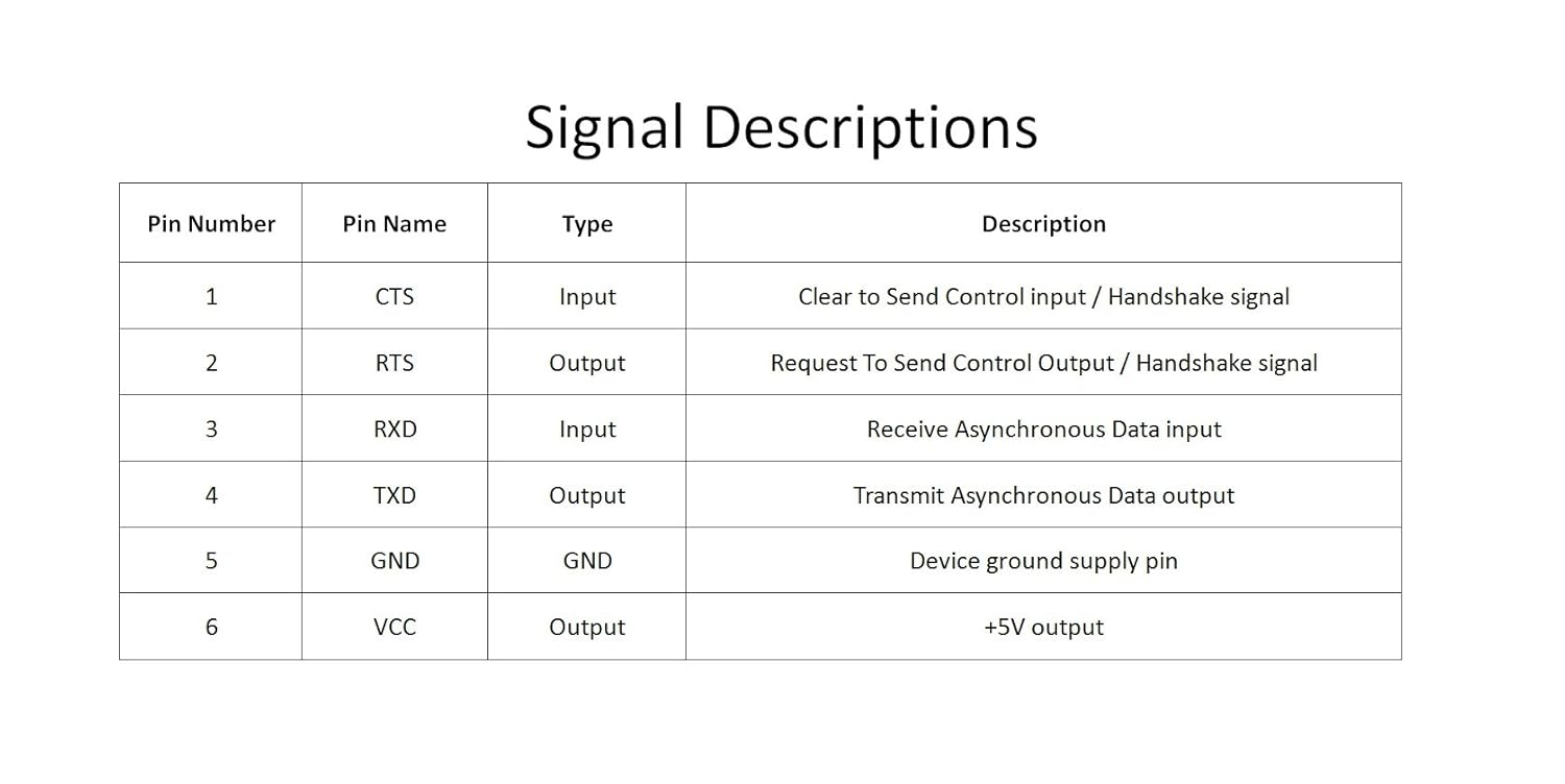
I have another question: The adapter has 6 Pins and the TinyG J14 has 4 holes. I can just ignore the extra 2 pins on the UsB interface?
What do you suggest for an easy way to attach them? Soldiering?
Thanks again!-
This reply was modified 7 years, 2 months ago by
May 18, 2019 at 8:02 pm #11424ModeratorBy the way – note on the schematic that RTS/CTS pins are not connected.
That should not affect Chilipeppr, might affect a sender app requiring RTS?CTS
May 18, 2019 at 8:44 pm #11425MemberThank you for all!
Now i feel more confident with this project.
I noticed that I misspelled the word Soldering in my post. The crazy auto-correct
May 18, 2019 at 10:32 pm #11426ModeratorIt looks like just Tx , Rx and Gnd are needed.
Connect with wire or by bending leads out of the way.
Soldering the interface directly into tinyG could be awkward to deal with.May 19, 2019 at 6:18 am #11427ModeratorI found the part on Amazon.
Best way to connect would be to solder in a 4 pin header then connect with the Dupont wires providedMay 19, 2019 at 5:55 pm #11428MemberStatus Update:
I soldered the 4 pin header on the board and connected the Usb adapter to it.
I used GND, RX, TX.
The connection to the computer went well and I launched Json which recognized the USB port.
I connected it successfully with chilipeppr but when i write $$ in the command line or when I click on the arrows to move the axis i don’t receive any answer.
It makes me think based on the tinyg installation tutorial that i need to connect the CTS port for have the complete communication between the software and the tinyg.
The problem is on the tinyg board I cant find where is the CTS pin hole , even looking on the schematic. I have a strange feeling that it’s right where the FTDI chip is on, and if so I am at the end of this Journey unless there is out there another way to use TinyG without CTSMay 20, 2019 at 8:42 pm #11431ModeratorI believe that disconnected RTS and CTS default to no flow control, which should not be an issue with low speed traffic.
Chilipeppr does not use hardware flow control.
Did you connect TX to Rx and Rx to Tx ?Describe to me what you see from the tinyG LEDs when you press the reset button
May 20, 2019 at 9:39 pm #11432MemberHello! thank you for the reply
I connected all like this:
RX pin from the Usb Adapter to the RX pin of tinyG
TX pin from the Usb Adapter to the TX pin of tinyG
GND pin from the Usb Adapter to the GND pin of tinyGWhen I press the reset button the PWM light stays on (No flashing)
May 20, 2019 at 9:57 pm #11433MemberWhen I press the reset button the PWM light Goes on and stays on (No flashing)
May 22, 2019 at 10:29 am #11434MemberI decided to just buy another TinyG board.
I like it too much and always worked great . -
This reply was modified 7 years, 2 months ago by
-
AuthorPosts
- You must be logged in to reply to this topic.