Home › Forums › TinyG › TinyG Support › 3 Phase DC Spindle Motor
Tagged: 3 Phase Spindle
- This topic has 11 replies, 3 voices, and was last updated 7 years, 10 months ago by
cmcgrath5035.
-
AuthorPosts
-
August 16, 2018 at 10:07 am #11072
Chris S
MemberGood morning,
I’m a beginner in the realm of CNC so if in my post I misuse any terms, misunderstand any core concepts, or am just generally wrong about how any of this works please feel free to correct me. I’ve looked around the wiki and the internet in general for the last day or so and can’t find a clear answer to my question, so here I am.We recently purchased two of these units:
https://www.bravoprodigy.com/engraving/desktop-cnc-router/desktop-cnc-engraving-machine.html
for a project and, while being a great hardware platform, for these reasons I’ve decided to replace the controller with a TinyG controller:
1. Control SW & GUI doesn’t meet our needs.
2. G code implementation is incomplete.
3. Spindle control is very limited, it only varies speed between 50 – 100%.
4. They pre-pend some Z axis movements to every G code sequence, this is irritating.After reading up a bit on CNC, G code, stepper motors, and available controllers I determined that the TinyG would be a perfect swap-in replacement for the existing controller. I was almost right, too. The power supply, fan, limit switches, emergency stop (reset), X, Y, and Z axis stepper connections were quite simple to identify and make and test.
Unfortunately the spindle stepper motor is causing some problems because, as my favorite new coworker figured out, it is an eight-wire 3 phase brushless DC stepper. Below is a picture of the motor label:
In case the image doesn’t display properly here it is in text form:
BLDCMotor BL42 Series
Type: BL42S24D4R002A5015
24VDC 80W 15000RPMIt’s a pretty good motor but is more powerful and faster than we need so if at the end of the day it’s easiest to just swap it with something TinyG supports I’m OK with that; please advise.
This is an example of how this motor works and should be controlled:
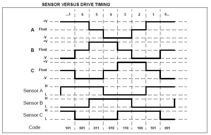
In short:
1 Wire for each phase (3 wires)
1 wire for each position sensor (3 more wires)
1 wire for VCC (+5)
1 wire for GNDfor a total of 8 wires.
Looking at the Motiontech motor diagram:
PIN Function
1 U
2 V
3 W
4 Vcc
5 GND
6 S1
7 S2
8 S3So my understanding is that TinyG does not natively support this kind of motor and that my only option is to build my own motor controller with six drivers which accepts PWM input from the TinyG. Please let me know if this is incorrect. (And the TinyG would likely overheat trying to drive this motor anyway, right?)
I’d rather not go down that road so I looked around here for posts about external spindle controllers and found this:
However:
1. It’s no longer available.
2. I’m pretty certain it’s not for 3 phase motors.What I’m looking for is one of two solutions/recommendations:
1. Is there a product similar to the controller above which makes use of this motor in conjunction with TinyG a simple installation?
or
2. Recommendations for variable speed spindle motors that plug in to TinyG and ‘just work’?
a. 0-10,000 RPM
b. Controllable RPM via G code
c. Low torque requirement; this is being use to polish, not remove materialSorry this post is so long but I wanted to include enough detail to get the help I need. Thanks for reading, let me know what you think or if you need more information.
– Chris
August 16, 2018 at 10:54 am #11073Zootalaws
MemberAny dc vfd motor controller with PWM that provides enough hz and amps should work.
24v and 80w is pretty small, though, without knowing what you want to do with it. What kind of collet do you have? That motor doesn’t seem to be designed as a spindle and I’m not sure what kind of runout you would expect to get – it isn’t a precision spindle motor. 3A isn’t going to do much work.
It may be easier to find a cheap air-cooled spindle with vfd\controller than to try and hunt down a compatible controller for such an unusual motor.
Just as an FYI, my small cnc router/Mills have, respectively, a 1050w and 2.5kw spindle.
The 2.5kw is water-cooled and the whole shebang was under $350 shipped.
If 80w is enough, you will find it hard to find a ‘proper’ spindle motor that small. 150w-400w is common, though, for pcb engraving and such.
Not a recommendation, just an example.
Depending on where you are in the world, you may have decent sources locally.
August 16, 2018 at 12:14 pm #11074cmcgrath5035
ModeratorI agree with Zootlaws observations on an 80W ‘spindle’.
Maybe OK for precision engraving, not for medium or heavy duty milling.If you decide to purse vfd based spindles, be aware that tinyG does not directly support them, but can with an interface circuit. Zootalaws can provide some guidance.
tinyG’s native spindle output is a 3.3v logic PWM signal, compatible with several spindle systems and controllers in the 400W range.
Here is an example, not necessarily a recommendationGiven a quick look at the BE3030, something in the 200-400W range should be adequate, if they will fit.
August 16, 2018 at 3:44 pm #11075MemberThank you for the replies.
The collet has two opposed set screws which press inward on a 4mm shaft. Nothing fancy.
That motor doesn’t seem to be designed as a spindle and I’m not sure what kind of runout you would expect to get.
I’m told that runout is not a concern.
We’re polishing a surface, not really milling. At this point I’m looking at turning a 9.5mm felt pad between 3,000 and 10,000 RPM with diamond paste and lubrication applied between it and the surface to be polished; 1.5 to 3.0 lbs downward pressure provided by a linear bearing. The z axis stepper motor doesn’t hold any weight because the spindle motor and a brass weight are mounted to a linear bearing on the z axis. I can provide a picture if you think it will be helpful.
…be aware that tinyG does not directly support them, but can with an interface circuit.
OK, thank you for confirming what I was beginning to suspect.
Thank you for the examples/non-recommendations. 😛 Now that I understand a bit more what to look for I can dig a little deeper.
August 16, 2018 at 4:27 pm #11076MemberAny controller with pwm is supported, like the one I linked before.
You could get away with any 10k-15k motor, as long as it provided enough HP, but that 80W one would struggle with drag on a 9.5mm pad, unless you’re lubricating it.
If it was me, I would spend $100 on a basic 250-400W DC motor and controller. It will give you bags of power and if you wanted to do more than polishing, you could turn it to any basic cnc task.An ER11 collet will handle a 4mm shaft.
August 21, 2018 at 8:09 am #11105MemberSo far, so good. Auto homing works and I’m running X, Y, and Z without issue. The motors are getting a bit warm so I need to figure out why. My new spindle motor, controller, and power supply should be here today.
I’ll post here with results.
Thanks again for the assist.
August 21, 2018 at 8:24 am #11106MemberMotors can get hot. They are on most of the time you are processing. If you think it’s too hot, you need a good heatsink, so if you can’t mount them to a metal plate or if they’re in a confined space, consider mounting a fan and heatsink or some external powered airflow over them.
Also, make sure you haven’t just cranked up the driver pot current to max. Especially for your iteration where it’s constantly fighting the drag of the buffer, it may be that you will just have to have it powered up, but its worth going through the tuning process.
I guess you’re going to have to work out a happy medium (no pun intended) to give you smooth low-drag running while still cutting the surface.
I wonder if some form of stepper amperage draw monitoring will be useful for monitoring drag?
August 21, 2018 at 9:50 am #11107MemberYeah, I failed to do one of the first configuration steps: Set the axis motor current limit potentiometers. Still can’t follow instructions, just like elementary school. 😉
All taken care of now, running quiet and cool.
Thanks.
PS – This TinyG board is amazing. It’s so flexible and configurable and easy to implement. If it’s as robust as we hope we’ll be in business.
August 21, 2018 at 10:36 am #11108MemberThat’s great.
TinyG are good boards, but be careful about shorts and stray voltage – anything 3.5v and up will kill it dead. I’ve got three and had no problems, but I’m careful.
It pays to put it behind something protective and give it decent cooling.
The drivers are cooled from the solder-pad side, so adding a heatsink on the top won’t do much, but they appreciate a bit of airflow across the bottom.
I’m right in the middle of seeing if I can power an orangePi zero from the fan pins, set to vmot so as to bypass the 12v regulator. If it works I will have a nice compact networked Tiny. I think I’ll put it away and call it a day.
Glad you sorted it all out.
If you need help with pwm, McGrath’s your man.
-
This reply was modified 7 years, 11 months ago by
Zootalaws.
August 30, 2018 at 9:45 am #11118MemberIt’s all working very well now, 100% functional using this motor/controller/power supply:
Here’s a table of commanded and actual revolutions per minute measured with a mechanically coupled tachometer, seems like it tops out at 10,000 RPM:
Commanded Actual
1000 720
2000 1832
3000 3110
4000 4340
5000 5570
6000 6649
7000 7552
8000 8301
9000 8915
10000 9442
11000 10013
12000 10530If it’s ever helpful to anyone here are the provisioning commands I’m sending at initialization:
G21 // Set the units to metric
$aAM=0 // Disable the A axis
$bAM=0 // Disable the B axis
$cAM=0 // Disable the C axis
$mt=10.00 // Set the motor idle timeout to 10 seconds
$1tr=31.4 // Set motor #1 (X axis) travel-per-revolution
$2tr=31.4 // Set motor #2 (Y axis) travel-per-revolution
$3tr=31.4 // Set motor #3 (Z axis) travel-per-revolution
$1pm=1 // Motor #1 (X axis) is always powered to hold its place
$2pm=1 // Motor #2 (Y axis) is always powered to hold its place
$3pm=1 // Motor #3 (Z axis) is always powered to hold its place
$3po=0 // Motor #3 (Z axis) polarity is NORMAL
$ST=1 // Set the limits switch type to NORMALLY CLOSED
$XSN=1 // Set the X axis minimum limit switch function to homing
$XSX=2 // Set the X axis maximum limit switch function to kill
$YSN=1 // Set the Y axis minimum limit switch function to homing
$YSX=2 // Set the Y axis maximum limit switch function to kill
$ZSN=1 // Set the Z axis minimum limit switch function to homing
$ZSX=2 // Set the Z axis maximum limit switch function to kill
$ASN=0 // Disable the A axis minimum limit switch
$ASX=0 // Disable the A axis maximum limit switch
$xTN=0 // Set the X axis travel minimum to 0 mm
$xTM=250 mm // Set the X axis travel maximum to 250 mm
$yTN=0 // Set the X axis travel minimum to 0 mm
$yTM=165 mm // Set the X axis travel maximum to 165 mm
$zTN=0 // Set the X axis travel minimum to 0 mm
$zTM=-60 mm // Set the X axis travel maximum to -60 mm
$xLV=80 // Set the X axis homing latch velocity to 10 mm/min
$yLV=80 // Set the Y axis homing latch velocity to 10 mm/min
$zLV=80 // Set the Z axis homing latch velocity to 10 mm/min
$xVM=1200 // Set the X axis velocity maximum to 1200 mm/min
$yVM=1200 // Set the Y axis velocity maximum to 1200 mm/min
$zVM=800 // Set the Z axis velocity maximum to 1200 mm/min
$xZB=2 // Set the X axis homing zero back off to 2 mm
$yZB=2 // Set the Y axis homing zero back off to 2 mm
$zZB=2 // Set the Z axis homing zero back off to 2 mm
$p1frq=5000 // Set spindle PWM frequency to 5000 Hz
$p1csl=0 // Set the clockwise spindle LOW speed to 0 RPM
$p1csh=12000 // Set the clockwise spindle HIGH speed to 12000 RPM
$p1cpl=0 // Set the clockwise spindle LOW phase to 0
$p1cph=1 // Set the clockwise spindle HIGH phase to 1
$p1wsl=0 // Set the counter-clockwise spindle LOW speed to 0 RPM
$p1wsh=12000 // Set the counter-clockwise spindle HIGH speed to 12000 RPM
$p1wpl=0 // Set the counter-clockwise spindle LOW phase to 0
$p1wph=1 // Set the counter-clockwise spindle HIGH phase to 1
$p1pof=0 // Turn off spindle PWM for devices that are not off at 0 phase. This tells the TinyG to comppletely turn off PWM when M5 received.Thank you for your assistance.
August 30, 2018 at 10:12 am #11119MemberNice little setup.
August 30, 2018 at 9:22 pm #11120ModeratorGood to see your progress.
One item, should you choose to do XYZ homing
Re-Read carefully https://github.com/synthetos/TinyG/wiki/Homing-and-Limits-Description-and-Operation
The tinyG homing command homes to Xmin, Ymin, Zmax so
$ZSN=1 // Set the Z axis minimum limit switch function to homing
$ZSX=2 // Set the Z axis maximum limit switch function to killNeed to be reversed so Zmax is the active limit.
There typically is no Zmin limit switch , although the Zmin limit input is used for probing cycles
-
This reply was modified 7 years, 11 months ago by
-
AuthorPosts

- You must be logged in to reply to this topic.