Home › Forums › TinyG › TinyG Support › Spindle: Spin/Sdir/PWM
- This topic has 10 replies, 2 voices, and was last updated 10 years, 1 month ago by
cmcgrath5035.
-
AuthorPosts
-
November 2, 2015 at 4:09 pm #8887
Vex
MemberTL;DR: What are the outputs of the Spin and Sdir?
A bit of background:I’m trying to figure out a way to integrate control of the spindle on my CNC machine via the TinyG and the Spindle Control Board (PCM21000A: https://www.minarikdrives.com/p-17350-pcm21000a.aspx). I do plan on expanding functionality of the spindle control depending on what outputs are available from the TinyG to do so. First and foremost control of the Spindle (1/2hp 10,000 rpm, universal motor stepped down via belt to spindle) rpm via the TinyG which will then be followed at some point in the future to incorporate dynamic braking and reversing of the spindle.
My current plan is to convert the Spindle PWM output from the TinyG to an analog signal of 0-10v via a DAC (http://www.ti.com/product/DAC813). Supply voltage will be taken care of by tapping the 24v ps for the TinyG and stepping it down.
My question (and I’ve tried searching the Git Wiki with no luck) is this: What are the outputs of the Spin and Sdir? Knowing those outputs will help me figure out if what I want to do is even possible.
November 2, 2015 at 8:49 pm #8888cmcgrath5035
ModeratorSpin lead is On/Off, following Gcode M03 and M05 . Think of it as a drive signal for an SSR that would turn on/off an AC spindle.
Sdir is logic high or logic low, depending on CW or CCW Gcode commands. Some controllers have Direction inputs.
Spindle PWM is Pulse width modulated logic signal, controlled by S commands in the Gcode. Not clear how you would attach a DAC. A low pass filter(duty cycle to DC converter) is likely all your need.
Give this item a look, sounds similar to your task
November 3, 2015 at 11:30 am #8892MemberThank you for your succinct response. It gives me some good ideas on how to implement dynamic braking and reversing. Back to the original discussion:
My original thought was to use a low-pass filter -> Regulated Voltage Booster but was directed to a DAC by an EE friend. (I was planning on using this circuit: http://playground.arduino.cc/Main/RegulatedPositiveVoltageBooster but he suggested using a dac and power supply to do the same thing without having to build the circuit myself). Adafruit sells a 0-5v PWM to analog converter breakout board, which I’m not opposed to, but would like the full range of 0-10v. Perhaps there’s a way to wire both boards to get the voltages I need?
TI has a white paper on PWM to Analog here: http://www.ti.com/lit/an/spraa88a/spraa88a.pdf
Which calls for usage of a DAC and lead me to believe using a DAC was a more appropriate route for my needs when coupled with the suggestion of my EE friend. Perhaps not? Ideally, I would like to minimize the number of extraneous circuits and wire runs (TinyG can’t output a 0-10v analog signal, right? :lol:)November 3, 2015 at 3:14 pm #8893Moderator(TinyG can’t output a 0-10v analog signal, right? :lol:)
Not directly, but the 3.3V logic PWM signal could be level translated with an open collector buffer to create a “10v logic” PWM signal which could then be filtered to DC in the range 0 to 10V.
I took a quick look at the references and see what they are doing. The first is a classic buck circuit, why bother? you have 12V available (the fan supply) which could easily be used to supply the converter.
My take is this interface does not demand a whole lot of precision; maybe you have an application where the spindle speed needs very precise control. The TI doc gives some good filter designs, perhaps just experiment with them, assuming you have the controller, or just hang a dc voltmeter on the filter output?
If you want to be bleeding edge adventuresome, have a look at tinyG2, a port to the Arduino DUE. The DUE has many available outputs that might better match your needs.
Caveat: some programming required 🙂
Start here:I suggest to do some Google searching on the SuperPID interface, several folks have shown interest and or have successfully implemented.
May 19, 2016 at 5:09 pm #9675MemberI know this is an old thread (one of my first on this forum), but I thought it important to post my results:
Using this circuit with slight modification, I was able to get the desired 0-10v output from gcode from the TinyG’s PWM output.
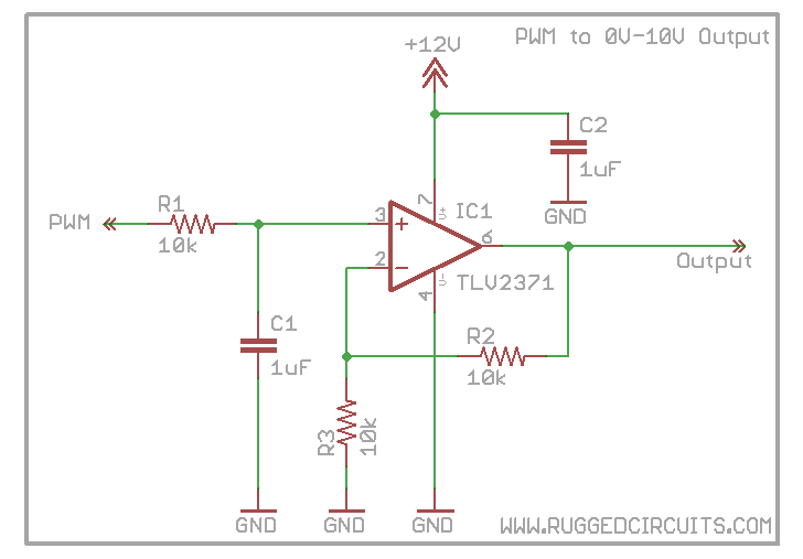
Walking through this with my EE friend, I found that the PWM outputs about 3.1v when set to 10khz and 1.0 phasemax. The only alteration I made to the above listed circuit is swapping out the feedback resistor (R2) for 22.25kohm resistor (I used 2x 15kohm resistors in parallel, plus an additional 15kohm resistor in series to the pair, for a total resistance of 22.25kohms when measured through my meter).
Here are my system settings for PWM output (I’ve only touched the CW versions–nothing else).
[p1frq] pwm frequency             10000 Hz
[p1csl] pwm cw speed lo               0 RPM
[p1csh] pwm cw speed hi           10000 RPM
[p1cpl] pwm cw phase lo           0.000 [0..1]
[p1cph] pwm cw phase hi           1.000 [0..1]
[p1wsl] pwm ccw speed lo           1000 RPM
[p1wsh] pwm ccw speed hi           2000 RPM
[p1wpl] pwm ccw phase lo          0.125 [0..1]
[p1wph] pwm ccw phase hi          0.200 [0..1]
[p1pof] pwm phase off             0.100 [0..1]
Slight modification to the feedback resistor may be required depending on others’ particular needs.
-
This reply was modified 10 years, 2 months ago by
Vex.
May 19, 2016 at 7:02 pm #9677MemberCaveat: Individuals will also need to adjust the p1_pl, p1_ph, p1_sl, and p1_sh according to your hardware.
May 20, 2016 at 7:15 am #9680ModeratorThanks for the post, we get many folks trying to solve this, I’ll be sending them here.
As drawn in the above, the circuit is a low pass filter followed by a unity gain amplifier, Gain – R2/R1.
Your stated solution, R2=22.5K, would have gain of 2.23.
Likely adequate for most VFD inputs.
As you point out, R2=30K would yield a gain of 3 and higher output at PWM=1.0.Good stuff
May 23, 2016 at 9:20 am #9694MemberCan the Sdir output handle 100mA? I’m beginning preparation for allowing m04 to function through the use of a dpdt relay that will integrate with the spindle control board (PCM20000).
May 23, 2016 at 4:02 pm #9696ModeratorA quick look at SAM3X specs shows Total DC current on All I/O lines at 100 to 150ms, depending on package type.
I woud not try it, use an external buffer or fet
May 25, 2016 at 1:37 pm #9716MemberHow many amps can the voltage regulator handle that powers the fan? The fairchild specsheet indicated in excess of 2 amps max (I’m not planning on pushing that much current, but I do not want to burn it out).
My current plan is to use the 12V from the fan to provide the voltage and current for a relay (spec sheet for relay states a current of 0.075A for the coil). With the fan and this planned relay I will be less than 0.5amp (fan is rated to 0.318amps, but is said to only pull 0.18amps), but the above circuit amperage pull is still unknown to me–I believe it to be in similar magnitude to the coil current (very little).
The long and short of it, is when should I start considering using the 24V from the Meanwell as opposed to using the regulated voltage from the fan?
May 26, 2016 at 7:34 am #9718ModeratorI believe the device is rated for 2A max, but you will have to watch out for dissipation (heat rise).
It was intended for powering the fan, not much else and is not terribly well heatsinked.
Even at 0.5A, 6W being dumped into the package and surrounding PCB will make things warm.Should work for short term testing, long term I would suggest you derive your relay supply from the main PwrSupply
-
This reply was modified 10 years, 2 months ago by
-
AuthorPosts
- You must be logged in to reply to this topic.