Home › Forums › TinyG › TinyG Support › Limit switches with TinyG2 + Arduino Due + GShield
- This topic has 17 replies, 3 voices, and was last updated 11 years, 5 months ago by
cmcta82.
-
AuthorPosts
-
February 8, 2015 at 7:56 pm #7342
SecondSource
MemberHi I hope this is the right place to be asking this question, if not please redirect me.
I am experimenting with driving a Shapeoko 2 through a GShield using TinyG2 on an Arduino Due, and using ChilliPeppr to send it GCode. It’s all working swimmingly, and now I have to hook up limit switches.
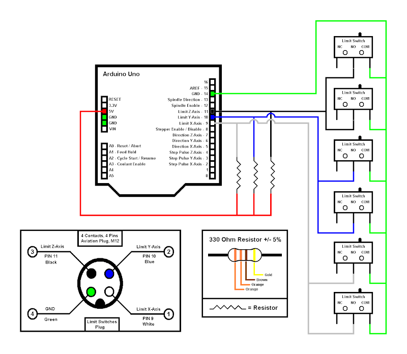
I imagined that it would be similar to GRBL on the Arduino Uno, in that there would be internal weak pullups set on pins 9,10,11, and I just use a NO switch as a trigger to pull the pin to ground.
I have based this on a diagram here:
I was unable to find any posts or diagrams that describe suitable Arduino Due limit switch wiring, so in the absence of this information I thought I would try a similar scheme.
Measurements indicate that pin 9-11 are all 0V, so either I don’t have the right pins or there are no internal pullups enabled. The system operates normally with all pins at 0V so clearly a LO state is not what is going to trigger a limit signal, unless it requires a low-going transition.
Before I damage something through experimentation, does anybody know the recommended wiring for limit switches and settings for the switch related parameters $ST etc. ? Thanks for any advice.
February 8, 2015 at 7:59 pm #7345MemberSorry not sure what happened, the image URL is
https://lh4.googleusercontent.com/-FhXABwKcb-I/UvMhBLTESlI/AAAAAAAADCI/kfE-f7jkrwc/s800/cnc_limit_switch_c3.pngFebruary 8, 2015 at 9:51 pm #7346MemberApologies, now that I test pins 9-11 they read 0v, 3v3, 0v3 respectively, which is another indication that these may not be the right pins to use. Any thoughts would be much appreciated.
February 8, 2015 at 11:03 pm #7347cmcgrath5035
ModeratorFirst, be mindful that the Due (and tinyGv9s) are 3.3V logic. so any external ‘weak’ pull-up must be to 3.3v, not 5V as in Uno space.
Second, Run CP from this
.
depending on your FW build ($fb) of tinyG2, this variant is necessary due to some issues observed in G2 with the CP start-up sequence.Necessary for build 71.04(by experiment), no experience with later builds(or earlier builds for that matter)Third, – In searching about, I realize that a Wiki Item like “Connecting to Due running tinyG2” isn’t there yet.
Info I can dig up say your might find the following function on the following pins:
DUE port Pin
PA10 3 RXD0 D19 Zmax
PA11 4 TXD0 D18 Zmin
PA12 5 RXD1 iL D17 Ymax
PA13 6 TXD1 2H D16 Ymin
PD4 17 TXD3 D14 Xmin
PD5 18 RXD3 D15 XmaxI highly recommend a test before committing, I have a somewhat older pin/port assignment and this may not be correct.
You can check with a voltmeter, but I would not expect there not to be pull-ups on a Due, so you may need to provide – to 3.3V!
-
This reply was modified 11 years, 5 months ago by
cmcgrath5035.
-
This reply was modified 11 years, 5 months ago by
February 11, 2015 at 7:11 pm #7361ModeratorYou will likely find this list easier to decipher:
Function Due Pin
pin_number kXAxis_MinPinNumber = 14;
pin_number kXAxis_MaxPinNumber = 15;
pin_number kYAxis_MinPinNumber = 16;
pin_number kYAxis_MaxPinNumber = 17;
pin_number kZAxis_MinPinNumber = 18;
pin_number kZAxis_MaxPinNumber = 19;pin_number kAAxis_MinPinNumber = 58;
pin_number kAAxis_MaxPinNumber = 59;
pin_number kBAxis_MinPinNumber = 60;
pin_number kBAxis_MaxPinNumber = 61;
pin_number kCAxis_MinPinNumber = 65;
pin_number kCAxis_MaxPinNumber = 51;They appear to be raw connection to pins on the uC. If there is a pullup, it is on chip not on board.
Derived from:
February 18, 2015 at 2:25 am #7399MemberThanks a lot cmcgrath5035, actually the information you supplied initially helped me a great deal; it made a lot of sense in conjunction with the Due pinout diagram found here:
http://www.robgray.com/temp/Due-pinout-A4.pngI was able to confirm that these are the correct pins and they have pullups internal to the processor. I have been testing the homing cycle with optical limit switches with some success.
But I have noted a situation where if I execute a homing cycle on say x axis only, using the X axis pulldown menu in chillipeppr, or with GCode manually, it homes correctly. But if I then immediately issue another homing command, it will start from zero and start moving negative and crash the carriage. It’s almost like when you start a homing cycle there is a period where the homing sensor is not being checked.
Maybe this is something for another thread?
February 18, 2015 at 4:23 pm #7407cmcta82
MemberHi @SecondSource, sorry to hijacking your post but can you explain how do you wiring your limit switch?i have also a tinyg2 running in arduino due with 75.02 firmware, i have already tried wiring my Ymin & Ymax NO Switch to GND and Pin 16 & pin 17, i try in chilipeppr configuring with Limit only and Home Only, with “limit mode only” i have random triggers and in home only when i try to homing my y axis nothing happens.
February 18, 2015 at 8:20 pm #7408MemberWhat kind of limit switch are you using? I am using an optical sensor, I found these on Ebay: http://www.ebay.com.au/itm/131135211065
The detector is a transistor junction that shorts when there is no obstruction in the gap, and when the light is blocked it turns off, and the pin’s internal pullup drags it HI. I had to remove a resistor on the sensor’s circuit board to isolate the output since I am driving it with 5V.
So basically the emitter is connected to arduino ground and the collector to the processor pin. I have mine set to Limit + homing.
Here are a few ideas, you might have already tried some of them:
1) Turn the motor supply off (arduino is still live), then put a multimeter or an oscilloscope on the pin and check that you are getting 3V3 when the switch is not activated, then trip your switch and check for 0V. Make sure it goes all the way to 0V if your switch type allows it. If you have a CRO, drive the motors and check that there are no spikes / dips / etc. you should have a steady 3V3
2) Try adding a stronger pullup to the 3v3 supply, say 1k or so? If you are using NO switches you will pull about 3mA only when the switch is closed. This might improve noise immunity.
3) Are the switch wires intertwined with the motor wires for neatness? Try running the wires away from the motors and their wires, or try using screened cable and grounding the screen. There might be crosstalk injecting noise into your limit switch line.
4) I forget what the default parameters are but try issuing $$ and make sure your switch_type set to NO. I have recompiled the code to hardcode the settings so it doesn’t revert after a reboot (no EEPROM on DUE)
Let us know.
February 19, 2015 at 3:53 am #7410MemberHi @SecondSource, thanks for your tips, i will try tonight after the work.
I´m using this limit switch It´s a microswitch with two contacts NO and NC, in mine is connected in NO contacts.
1. I will try tonight
2. Can you explain how do you suggest to connect them?
3. I use shielded cables but like i´m still testing Tinyg2 i have not connected the shield to ground, i can try it.
4.I have to do the same like you, i’m still sending all settings manualy with chilipeppr…How do you set the NO or NC contact settings?i try sending the same command from tinyg but is not recognise, i send the command $ST=0Was cool if the forum had a section dedicate to tinyg2:)
February 19, 2015 at 8:45 am #7411ModeratorDedicated G2 sub-forum? Maybe in future, for now use this.
You may find this helpful (by downloading it you acknowledge it’s DRAFT status). I’ll clean it up after review by the Synthetos folks and make available in editable (svg) form, so folks who custom compile pinouts can have their own. I got dizzy last week trying to explain this, so made this diagram from the familiar DUE base
Without doing a lot of looking, I’ll make two reasonable assumptions about the Due ports: 1. they probably have ESD protection structures on chip and 2. whatever looks like a pull-up is likely not a high wattage structure.
My suggestion would be to implement limit switch interface similar to what is used on tinygv8. Schematics can be found here (hint: 2.7K and 0.22uF)Also make sure you see that build G2 75.02 now has individual switch settings, min/max *6 axes that need to be configured correctly.
If issues continue with homing, perhaps a post at
Be sure to describe how you have set up the switches and how you builtG2
And remember, ground shield at only one point, probably DUE end for all shields
-
This reply was modified 11 years, 5 months ago by
-
This reply was modified 11 years, 5 months ago by
February 19, 2015 at 2:32 pm #7415MemberHi cmcgrath5035,
Thanks a lot, it will be very helpful, and it will be a nice poster to put over the CNC to help me during my troubleshooting and tests in Tinyg2. i will try to design firstable in fritzing and share with you just in case. Thanks again.
I already tried the touch plate widget in chilipeppr and it´s working great.
February 19, 2015 at 5:28 pm #7417MemberHi,
Can you take a look to the circuit? i don´t have problems with pinout in due, your pdf is very easy to understand, just to confirm if the circuit are ok, like you suggest i take a look in tinyg V8 circuit. i also add my touchplate.
http://1drv.ms/1MC0Zi0February 20, 2015 at 12:23 am #7422Membercmcta82 your schematic looks fine in principle, but note that the capacitors are the wrong way around, you want the – side to GND and + side to the port pin.
You probably took your capacitor symbol from the tinyG schematics; I am guessing they are using 0.22uF ceramic non-polarized caps on the tinyG board, and sometimes non-polarized caps are shown with a straight line next to a curved line, despite that more commonly being used with polarized parts. On the tinyG schematic they seem to add a + symbol to indicate the part is polarized and omit it when NP.
In any case you have the right idea, let us know if that solves your problems.
February 20, 2015 at 6:57 am #7423ModeratorI agree with SecondSource, you are in good shape, but must comment I can’t read the pin numbers on the DUE.
If I assume you are using Eagle to draw this, you should pick a non-polarized cap symbol.
0.22uf ceramic caps are not polarized, doubt you have 0.22uf electrolytics.
The tinyG caps are SMT chip ceramics.This is the first time I have viewed a file in OneDrive Cloud. I don’t particularly like the viewer, tends to cut off(obscure the top and bottom when you try to Zoom. But I managed.
February 20, 2015 at 3:52 pm #7424MemberI will try tomorrow in a breadboard, you are right i make a mistake when i read the tinyg circuit:( but i have this polarized electrolytics caps from a kit i buy a few months ago. i will update the circuit in dropbox to not confuse other users.
and again thanks for you help and sorry SecondSource to “stole” your post
-
This reply was modified 11 years, 5 months ago by
-
AuthorPosts
- You must be logged in to reply to this topic.